
More than 85 Years History of the Pipi-Stop
1932 — First alarm-system invented by Ernst Bieri in Laupen/BE (Switzerland)
Ernst Bieri invented the alarm-system AntiNass (Pipi-Stop) in order to help his little brother and 1932 carried out his first attempts successfully. That same year he talked about his invention with the general practitioner, Dr E. Müller-Pradervand in Laupen (BE) and demonstrated him his alarm-system. The doctor was very interested in this device , because he knew how resistent nocturnal enuresis is to all therapies that were not founded on a suggestive basis. Dr. Müller-Pradervand used regularly and successfully the alarm-system with his patients.

1935 — Patent application on August 5th 1935
On August 5th 1935, Ernst Bieri submitted his request for the registration of a patent. This was accepted and published under Nbr 185773 on November 2nd 1936.
Since then successive developments allowed to improve his alarm-system on a regular basis.
1974 — Take over of the company by the children of the inventor under the name Electro-Bieri & Cie
1974 Paul and Sonja Bieri (respectively son and daughter of the inventor) and Patrice Hämmerli (future husband of Sonja) joined forces to take over the firm of the inventor. Together they founded a general partnership under the name Electro-Bieri & Cie.
2009 — Fondation of Melebi SA
2009 the same team, in the meantime reinforced by Ursula Bieri (future wife of Paul), chosed a change of the structure and founded Melebi SA.
This name encompasses the terms medical – electronic – bieri.

2017 – New Management and Relocation to Bienne
The four founders of Melebi SA (the children of Pipi-Stop inventor Ernst Bieri and their spouses) have stepped down to make way for their children. In August 2017, Pascal Hämmerli and Christine Calderara took over Management of the company.
Melebi SA has been operating from their new address in Bienne since September 2017.
Museum: the precursors of the actual Pipi-Stop
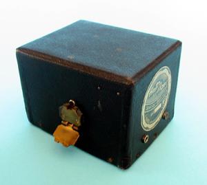
1934 – Cardboard box with memorization of the alarm
- One of the first bed-wetting alarms
- Powered by 3 batteries of 4,5V each
- The sound (alarm) was produced by a buzzer (principle of an old telephone bell)
- A special electromagnetic relay with a flap served as memorization for the alarm. The acoustic alarm could be switched off by shifting this flap in an upper position and therefore reactivating the system for the next event
- When the bed-wetting was detected, the flap, released by the relay, fell down and the alarm sound was activated and memorized
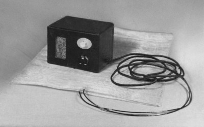
1935 – Cardboard box with an acoustic and optical alarm
- This device was already equipped with an acoustic and optical alarm
- A special electromagnetic relay with a flap served as memorization for the alarm
- The acoustic alarm could be switched off by shifting this flap in an upper position and therefore reactivating the system for the next event
- When the bed-wetting was detected, the flap, released by the relay, fell down and the alarm sound was activated and memorized
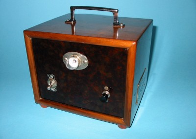
1936 – Wooden enclosure with acoustic and optical alarm
- Acoustic and optical alarm
- The sound was produced by a telephone receiver powered by an alternating current
- The system was connected to an 220V/110V outlet supplying a transformer with a secondary voltage of 10V
- After a releasing of the alarm, a self-holding relay memorized the sound and the light
- By pulling out a button the sound was desactivated but the light remained on during the drying
- By pushing the button in, the system was set in an operational state
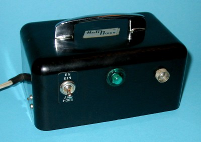
1959 – Backelite(R) case with acoustic and optical alarm
- Acoustic and optical alarm
- Mains 220V powered with transformer
- The sound was produced by a telephone receiver powered by an alternating current
- After a releasing of the alarm, a self-holding relay memorized the sound and the light
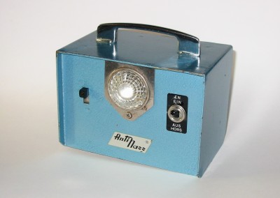
1964 – Metallic case, first fully electronic device
- Acoustic and optical alarm
- This first fully electronic device was equipped with 5 Germanium transistors
- The system was powered by three mono-cells with 1,5V each
- The sound was produced by an electronic oscillator connected to a small loudspeaker
- Three different levels of volume could be adjusted with a sliding switch
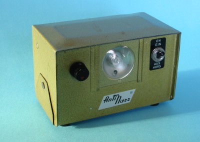
1972 – Metallic case with LED
- Acoustic and optical alarm. Volume adjustable by potentiometer
- This device was equipped with a LED (Light Emitting Diode) to indicate the active status. This had a non negligibly psychological effect
- The use of a LED in 1972 was a little revolution because LEDs where only available on the market some years since then and where very expensive. Also, there where only red LEDs available
- Power supplied with 9V by 2 batteries of 4,5V each
- The sensibility of this device was adapted to a detector witch consisted of parallel assembled metallic strips
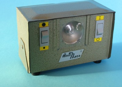
1974 – Metallic case with test switch
- Alarm acoustic and optic. Two sound volume and test switch
- Powered by 9V with 2 batteries with 4,5V each
- Very low power consumption
- This device was used with a detector with parallel lying metallic strips
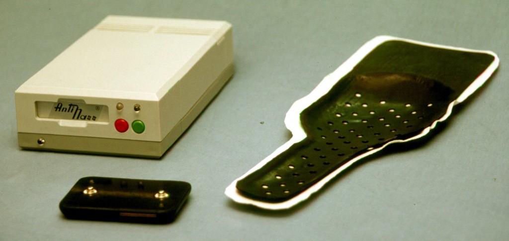
1990 – First tests with a wireless system
- Prototype of a wireless system transmitting the alarm from a transmitter (worn by the child) to a receiver (on the night table). No more cable!
- Acoustic and optical alarm. Sound adjustable continuously
- The receiver was powered by a 230V source
- The transmitter was equipped with accumulators which could be charged during the daytime, inserted in a slit in the receiver
- The detector consisted of two perforated conductive synthetic shells, isolated from each other by a fleece
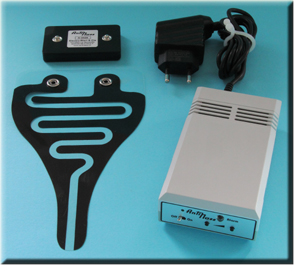
2000 – Wireless transmission with transmitter and receiver
- State of the art electronic with integrated circuits in SMD (Surface Mounted Devices) technology in the transmitter
- Wireless transmission of the alarm from the transmitter (worn by the child) to the receiver (on the night table). No more cable!
- Alarm acoustic and optical (high energy red LED). Volume adjustable by two push buttons and memorization of the the last adjustment even in the event of power loss
- Receiver powered by 230V mains
- Transmitter energized by Lithium batteries
- The detector consists of a polyester-foil printed with conductive stain and used with a paper napkin
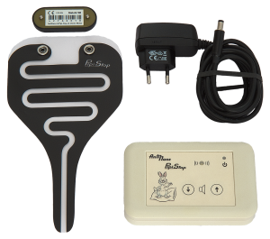
2010 – Wireless transmission with a small transmitter and receiver
- State of the art electronic with integrated circuits in SMD (Surface Mounted Devices) technology
- Wireless transmission of the alarm from the transmitter (worn by the child) to the receiver (on the night table)
- Alarm acoustic and optical (light, white LED). Volume adjustable by two push buttons and memorization of the the last adjustment even in the event of power loss
- Mute mode for the use with the vibrating wristband VIBRA
- Receiver powered by 230V mains
- Transmitter energized by only one Lithium battery
- The detector consists of a polyester-foil printed with conductive stain and used with a paper napkin
Museum: Detectors in the course of time
The detector was always the critical point. Without a safe and quick recognition of the wetting, the desired learning effect is not reached.
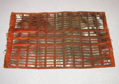
1934 – Metallic strips woven in an oil soaked fabric
Metallic strips woven in an oil soaked fabric, isolated from each other: this was the first detector used with AntiNass.
Each second strip is connected and form a comb. Two nested combs form each electric pole of the detector.
Many different layouts where tested
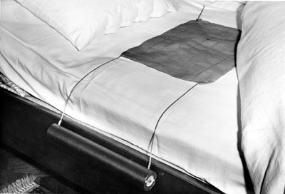
Prototype of a detector equipped with two cylinders. These could contain the batteries on one side and the circuitry on the other and could be rolled up for shipment.
1936 – Detector consisting of two perforated metallic sheets
This detector consisted of two perforated metallic sheets, laid on top of each other, isolated by a bed sheet or a piece of fabric. This detector could more easily be cleaned then the oil soaked fabric but could not be rolled up for shipment and was less comfortable.
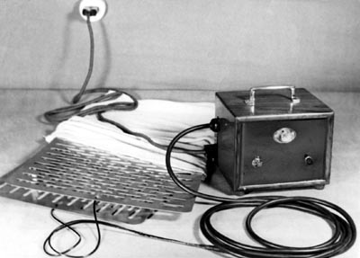
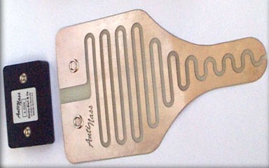
1960 – Conductive comb made of aluminum strips
The detector consists of aluminum strips alternatively connected to one of the electrical poles.
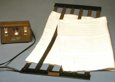
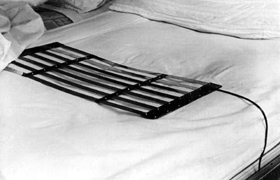
1974 – Conductive comb made of stainless strips
The detector consists of metallic strips of stainless steel which are connected alternatively with one of the electrical poles. Due to the flexibility of these strips, the detector offered a comfortable usage. Each strip was isolated from the other by a piece of fabric.
2000 – Detector worn in the underpants
Prototype of a gold plated detector with transmitter worn in the underpants (slip).
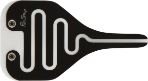
2010 – Detector worn in the underpants
The detector consists of a polyester-foil printed with conductive stain and used with a paper napkin.
Patent and schematic of the first alarm-system AntiNass

Patent Nbr. 185773: submitted on August 1st 1935 and publicated on Novembre 2nd 1936
Patent concerning a device to overcome bedwetting, developed by Ernst Bieri and submitted on August 5th 1935, registered on August 15th 1936 and published on November 2nd 1936.
The brand AntiNass was used and protected since the beginning.
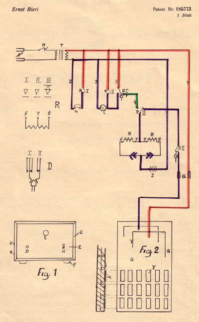
Schematic of the patented alarm-system AntiNass
This schematic was part of the submitted patent on August 5th 1935 and registered on August 15th 1936. It corresponds to the device in the wooden enclosure.
The most important parts are:
R – the relay with 3 contacts (buzzer, light and self-holding)
D – the push-button allowing to switch off the sound (the light remains on)
G – the urine detector
